home rep-tile demo hardware credits

Introduction to the Hardware System.

The physical Rep-Tile device is designed as a standalone educational gaming console. Built around an ESP32 microcontroller, it coordinates multiple custom components, wireless readers, dual displays, sound feedback, and a unified state management button to enable active gameplay.

The unit is housed in a custom CAD-designed, 3D-printed chassis. It supports physical wooden player mats, custom laser-cut tile sets, and smart RFID game tokens that register inputs instantly.


Build it Yourself! ↓
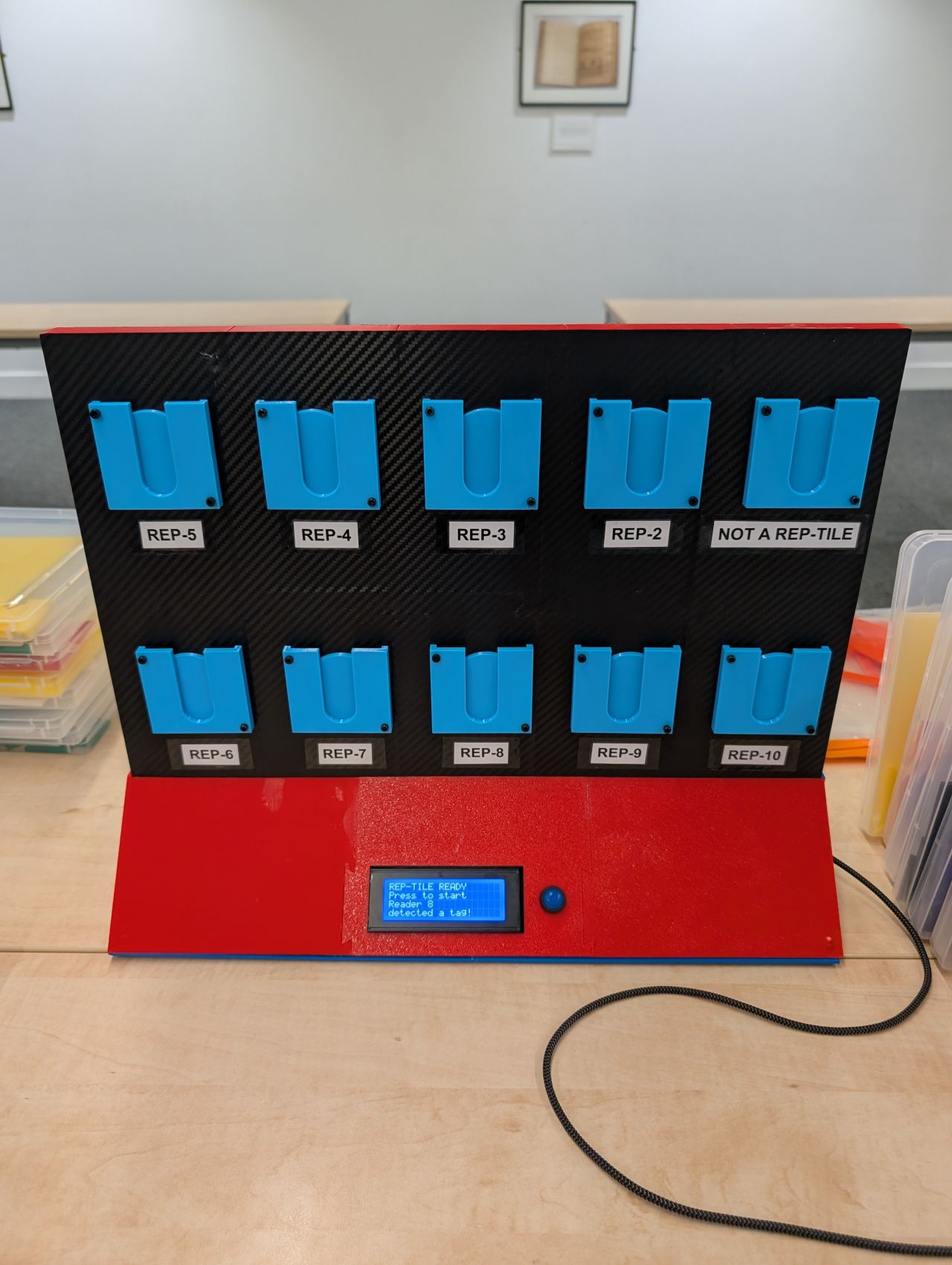
Rep-Tile System Head-on

The Subsystems

Under the hood, Rep-Tile coordinates several distinct electronics modules over I2C and SPI buses to manage wireless tags and gameplay states.


PN532 NFC Reader Array

The game features 10 PN532 NFC reader modules sharing the communication lines. Individual white LEDs sit directly above each reader. The system utilizes custom library implementations for high-frequency reader scanning, enabling it to read multiple smart cards simultaneously (up to two per reader node — one Blue and one Red).

Key Components:

10x PN532 Board SPI/I2C Multiplexing Active Indicator LEDs

Dual LCD Status Screens

Two 20x4 I2C character LCD displays are wired together. They share the same address (0x27) and bus to mirror live game status. They display current round targets, ticking game timers, and real-time player scores.

Display Features:

Dual 20x4 I2C Screens Mirror Output Layout Auto Text wrapping

Organiser Dashboard Portal

The ESP32 hosts a local WiFi access point (SSID: REP-TILE). Connecting to 192.168.4.1 loads the administrator panel, allowing organizers to configure round times, toggle Random/Manual difficulty modes, add/remove shapes, and monitor active reader card states.

Web Capabilities:

ESP32 AP Host Live RFID Card Grid NFC Token Programmer

Piezo Audio & State Controls

A high-precision piezo buzzer plays musical alerts for gameplay events (countdown beeps, success chimes, round end klaxons). A single physical button acts as a state router, allowing organizers to advance the round, clear scores, or force a hard reset.

Interfaces:

Active Piezo Buzzer State Routing Button Game Over Fanfare

Fabrication Downloads.

Download the CAD models and the Arduino firmware used to drive the Rep-Tile project.


💻 Embedded Firmware


Arduino sketch and custom PN532 library source files:


• rep-tile_lcd.ino
• custom PN532 source (.cpp)
• custom PN532 header (.h)


Build Guide: Step-by-Step

Follow these instructions to source, print, assemble, and program your own Rep-Tile game unit.


Step 1: 3D Print the Enclosure

Download the 13 unique enclosure files listed in the Downloads section above. Slice them using standard slicer software (like Cura or PrusaSlicer) with PLA or PETG filament. Print the recommended quantities for each file (e.g., 20 Answer Tokens, 20 Holders, 3 Top/Bottom Middle panels, etc.) for a total of 57 printed parts. We recommend using 20% infill (gyroid or grid) and enabling supports for panels containing ports.

Step 2: Wiring and Electronics Assembly

Connect the components to your ESP32 microcontroller using the following pin map:

Step 3: Upload the Custom Firmware

Open the Arduino IDE and ensure the Adafruit_PN532 library is installed. To handle multiple cards simultaneously on the SPI bus without conflicts, copy the custom implementations of Adafruit_PN532.cpp and Adafruit_PN532.h from the Downloads card into your local Arduino libraries folder. Open rep-tile_lcd.ino and upload it to the ESP32.

Step 4: Organizer Dashboard & Calibration

Upon boot, search for the WiFi access point named "REP-TILE" (password: notareptile) using your computer or phone. Open your browser and navigate to http://192.168.4.1. Toggle write mode in the panel, select Blue/Red, and tap the blank RFID tags against the physical readers to program the player tokens.